This project is based on the fantastic work “Mike’s Talking Skull Project (JawDuino)” (no relation).
Table of Contents:
Components
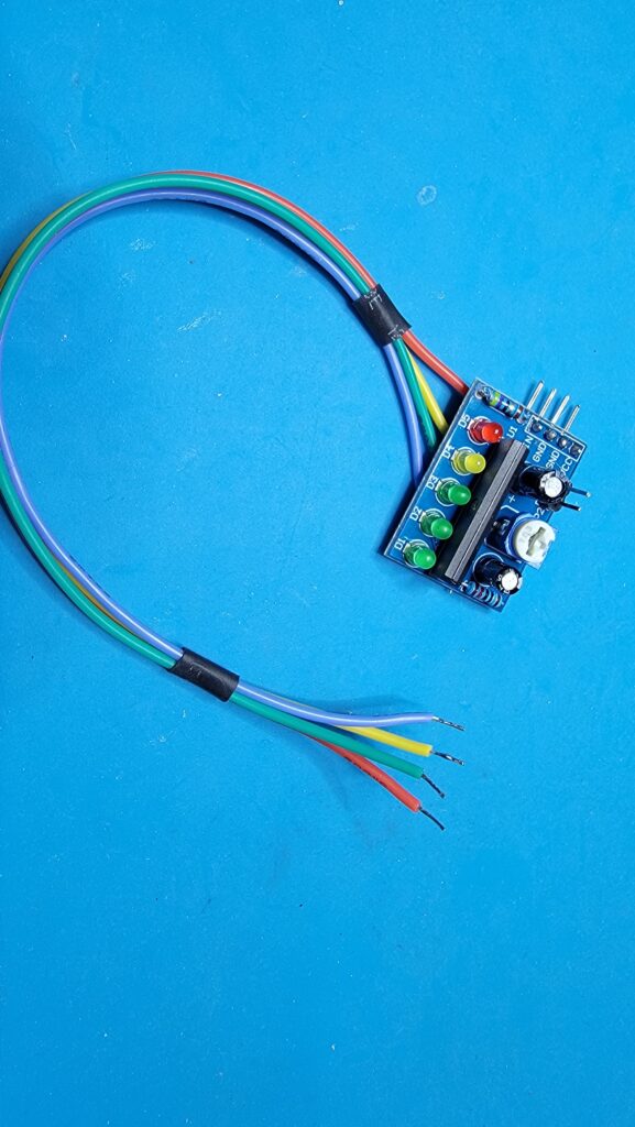
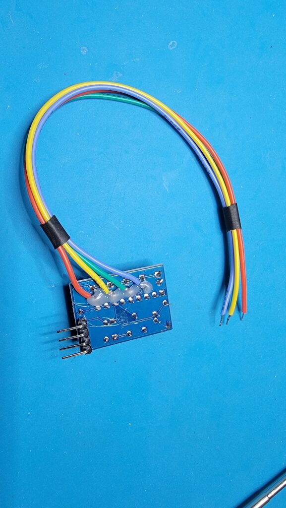
I used the same idea as he did, basing the circuit around the The KA2284 LED sound meter module, but I ran 4 wires instead of 3. I also desoldered and removed the four straight header pins coming out the top of the KA2284 and replaced them with right-angle pins coming out the bottom (more on that later). I put four dots of hot-glue over the signal wire solder points to reduce strain on the joint. Please note, the module says it can take anywhere from 5-12v dc to power it. Based on my experience though, if you use more than 5v, it will overload the signal lines going to the Arduino.
I have a bunch of mp3 player modules (TDB380 v1.0), so I started looking for ways to leverage them to play and animate sound.
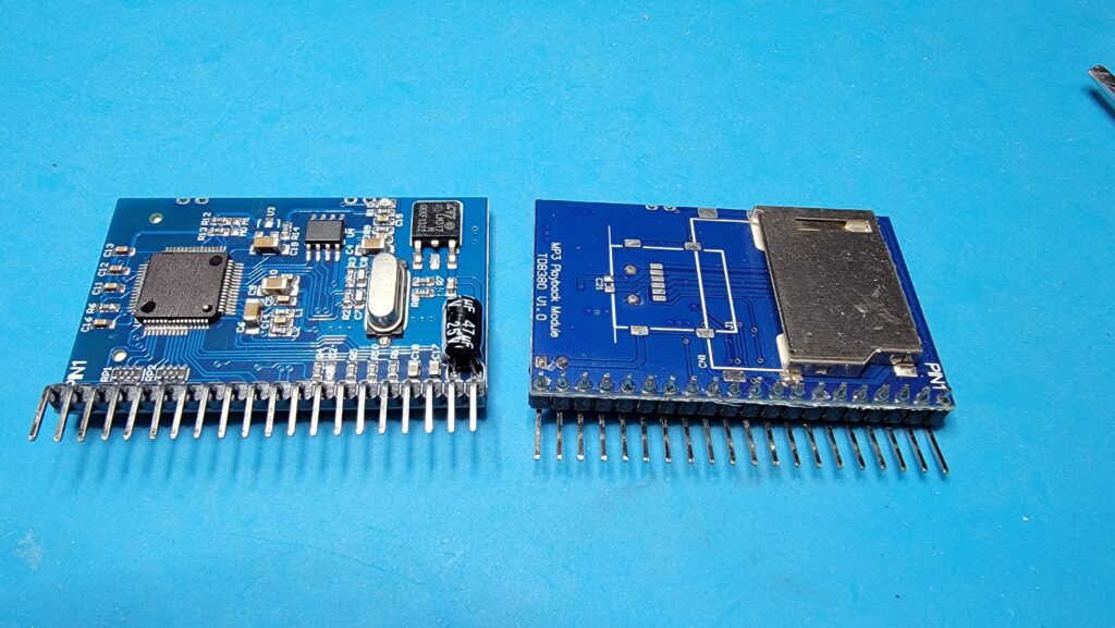
This article is extremely helpful in this regard – to prove the board can work: Interfacing TDB380 Mp3 Module With Arduino : 3 Steps – Instructables
The board is capable of running in several modes, depending on how the M0 and M1 tabs are set on the board. At first I tried using it by pulling down P0 through P7 to play specific tracks. This works okay if you only want it to play a single track. It gets weird if you want to switch — plus it could eat up a lot of i/o ports on the Arduino. So, I started looking at ways to hook up to it serially. The downside of that method is it cuts out your ability to use the Serial.print interface for debugging. That’s when I found this thread on the Arduino forum: Created a library for the MDFLY MP3 module (TDB380) – Using Arduino / Audio – Arduino Forum . The really amazing thing is this guy distilled the interface to this board down to a simple TX (transmit) and Busy pin. And the TX pin can be ANY digital output, (not pins 0 and 1). This is a major game-changer. Another super-important thing to keep in mind. In order for the sound module to receive the serial communication, it MUST share ground with the Arduino.
There are a few idiosyncrasies to this board, chief of which is the file naming convention on the sd card. The protocol calls for names like A001, A002 etc. But the reality is that the board is extremely stupid and doesn’t care what the file name is. If you tell it to play track 1, it will play whatever file is located in the first position of the sd card’s FAT table. If you start with an empty sd card and add the files one at a time in numerical order, then you’ll get the files you want played in the proper order. If you add files later, or copy them at random, you’ll waste a lot of time chasing gremlins.
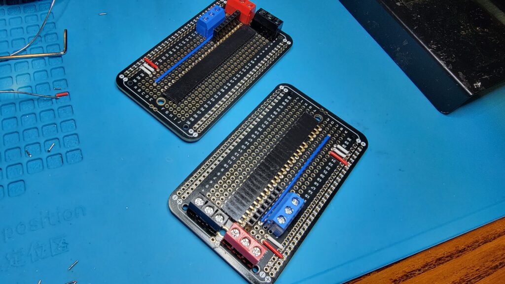
Often with Arduino projects, you have a lot of wires running between the computer and the various components. This starts to get unwieldy when you blend the projects together. For this one, two power wires go to the TDB380, then the TX and Busy wires. Not to mention the Left and Right stereo outputs. The KA2284 needs 4 wires running to it, plus another 4 running out of it. So, I started creating “shields” (custom pcb boards) that could plug components together with minimal loose wires. An example is the audio shield below.
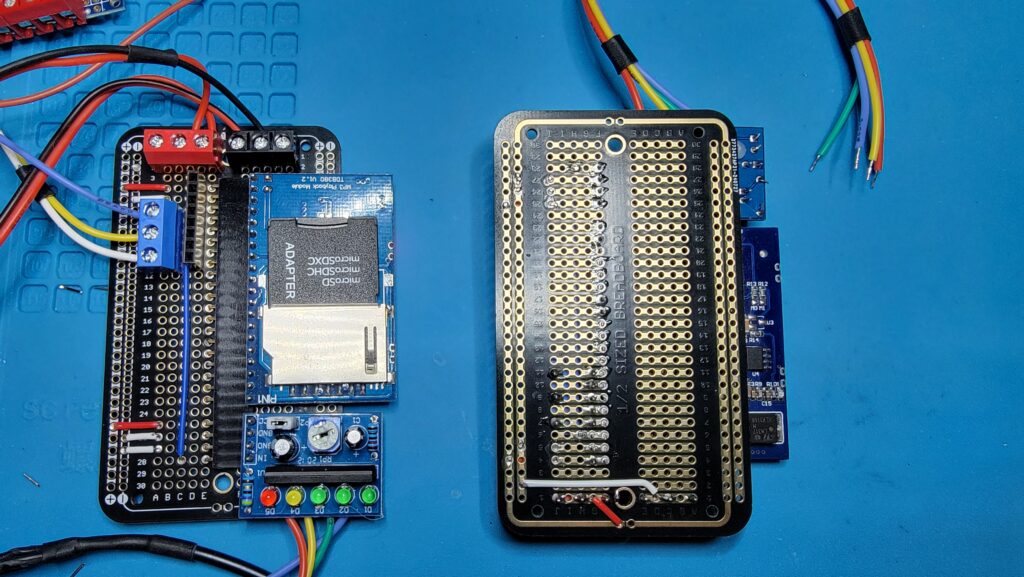
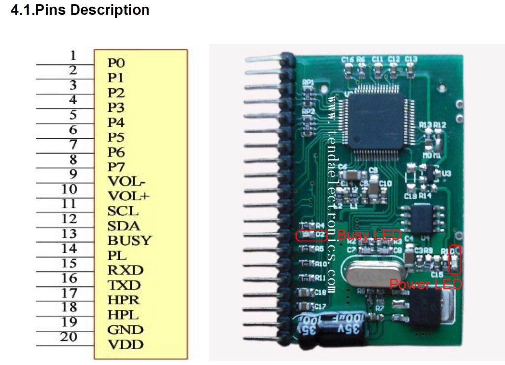
When running the TDB380 in serial-player mode, you only need to care about pins 13-20 on the module. 20 and 19 are the + and – dc power input. The spec sheet for the module says this should be 12 volts. But it works fine with only 5 volts. And since the KA2284 also works best with 5 volts, they can share the same power. Pins 18 and 17 are the Left and Right stereo outputs. For our solution, we’ll use the Right channel to send the actual audio to the prop. The Left channel will send the signal to the KA2284 to interpret for jaw movement. Pin 15 is the RX channel for serial communication to the TDB380. Note: It Receives the signal that is Transmitted from the Arduino. Finally, Pin 13 is the Busy pin — it sends the signal back to the Arduino that something is currently playing.
Here is the step-by-step order I suggest for these boards. You will need:
Parts List
- 1 x ElectroCookie ElectroCookie Prototype PCB Solderable Breadboard
- 3 x 3-pin 5mm/0.2inch Pitch PCB Mount Screw Terminal Blocks
- 1 x 8-pin female straight header block
- 1 x 20-pin female right-angle header block
- 1 x 4-pin female right angle header block
- For the wires, I got some of these, but you can use any small solid-core wire you have. Note: the measurements below are the insulation size between the holes. Make sure to leave 3-5mm bare wire on either side of the insulation.
- Front Wires:
- 1 x 56mm patch wire (blue)
- 2 x 10mm patch wire (red)
- 3 x 6mm patch wire (black)
- Back Wires
- 1 x 8mm patch wire (red)
- 1 x 28mm patch wire (black)
- Front Wires:
Assembling the Shield
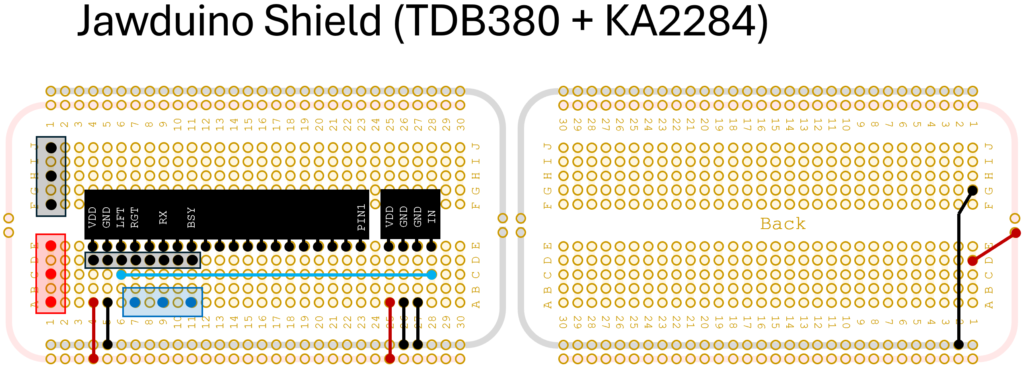
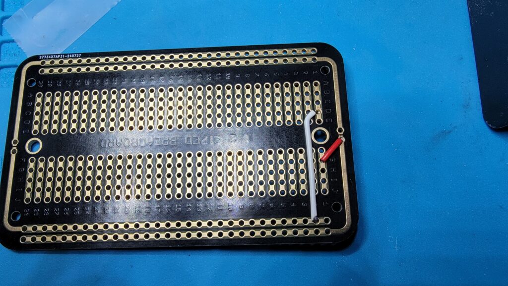
- Solder the two Back Wires on the back of the board first. The black wire goes from G1 to the negative Ground bus. The red wire goes from D1 to the positive Power bus. Note: The legs of the wires will poke through the front side of the board. You must trim these legs flush with the surface (as the screw terminals will sit on top of these).
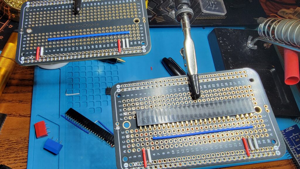
- Solder the Front wires in place. Blue wire from C6-C28. Red wires from the positive power bus to A4 and A25. Black wires from the negative power bus to A5, A26 and A27. Trim the legs to a reasonable length.
- Solder the Right-angle header(s) in place. Note: in the first version of this board, I used a 20-pin (spanning E4-E23) and a 4-pin (spanning E25-E28). In the pictures above, I used a single 25-pin header, spanning holes E4-E28, with the pin on hole E24 removed.
- Solder the 8-pin header into place, spanning holes D4-D11. This is used to carry the important signals (TBD380 pins 13-20) to an optional upper shield.
- Solder a 3-screw terminal block on row 1 in holes A1, C1, E1 (this is for +5v). Mine was Red.
- Solder a 3-screw terminal block on row 1 in holes F1, H1, J1 (this is for Ground). Mine was Black
- Solder a 3-screw terminal block on row A in holes A7, A9, A11 (these will align to pins 17 (Right Channel), 15 (RX), and 13 (Busy) on the TDB380). Mine was Blue
Wiring to the Arduino
For my setup, on the Arduino, I used DO Pin 10 for TX, and DI Pin 13 for Busy. I ran a wire from the blue terminal block (TDB380 pin 13) (busy) to Digital Pin 13 on the Arduino and configured as an INPUT. I ran another wire from the blue terminal block (TDB380 pin 15) (RX) to Digital Pin 10 on the Arduino and configured as an OUTPUT.
The four leads from the KA2284 are run to Pins A0 (blue wire), A1 (green wire), A2 (yellow wire) and A3 (red wire).
The audio shield will need 5volts dc supplied to it, but I don’t recommend using the 5v output from the Arduino itself. It needs its own 5v power supply. Note however that you MUST have a common ground between the Arduino and the audio shield. Therefore, I ran power from a 5A 5Volt power supply, running the Positive (+) leads to the audio shield and the VIN pin on the Arduino. I ran the Negative (-) leads to the audio shield and the GND pin on the Arduino.
Audio Amplification
The signal from the TDB380 is strong enough to be heard through headphones, but not loud enough on its own for a speaker.
The Right Audio Channel (TDB380 Pin 17) runs from the Blue terminal block to the Positive Input on an Audio Amplifier module. A separate ground wire is run from the Audio Shield to the Negative Input on the Amplifier.
I have played around with 2 amplifiers. Here are two options:
LM386 Mono Audio Amplifier Module
When I first found this module, I was thrilled. It was cheap, and would boost the sound 200x. It was promising, and I designed the first Smart Head to have one nestled in the skull to provide local amplification for the in-head speaker.
It turns out this was a bad plan. By the time the audio signal found its way from the MP3 player to the amplifier, it had gone through a lot of noise-inducing stuff, and the signal that was being amplified was full of distortion, pops, and crackles.
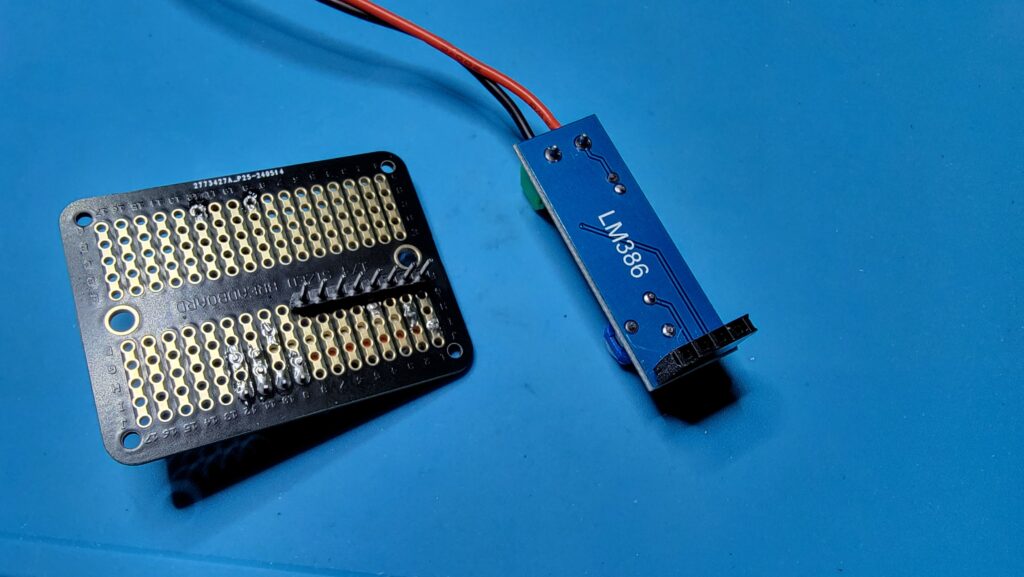
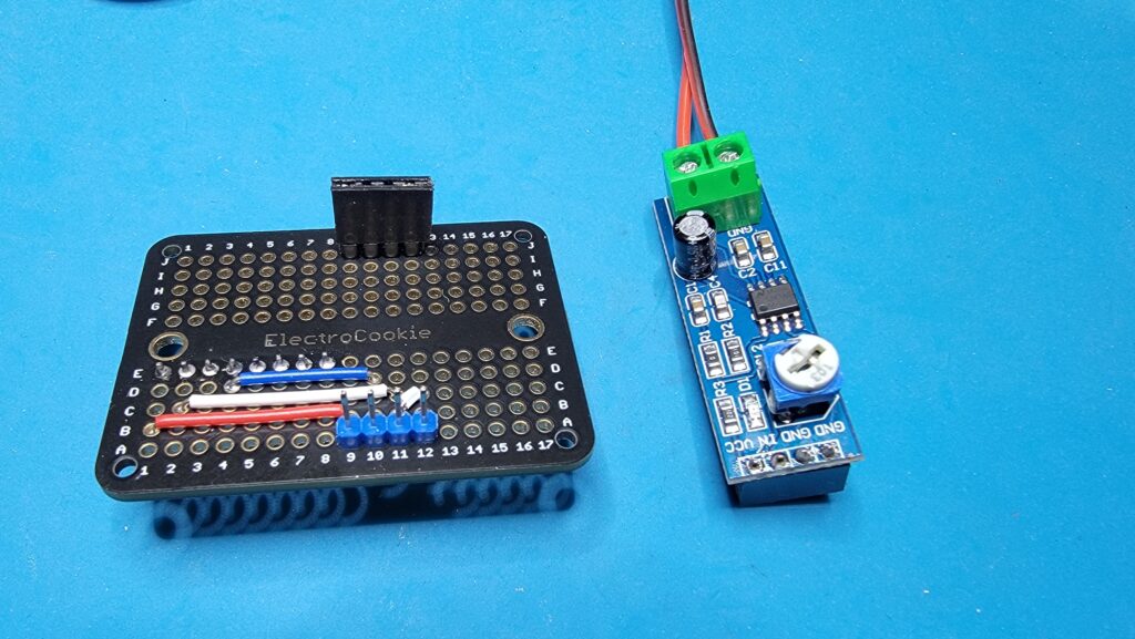
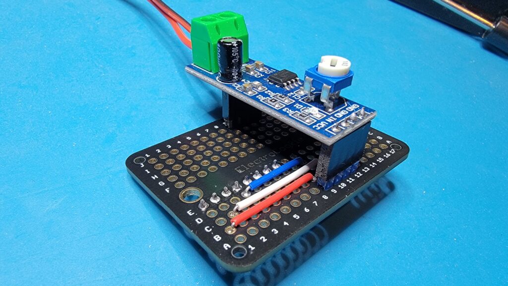
The answer was to move the amplifier closer to the source, and just run the speaker signal up to the head. That’s why I created a piggyback shield for the LM386 to plug onto the 8-pin header we added to the Audio Shield.
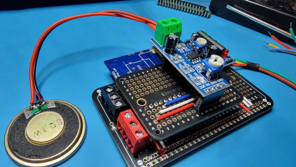
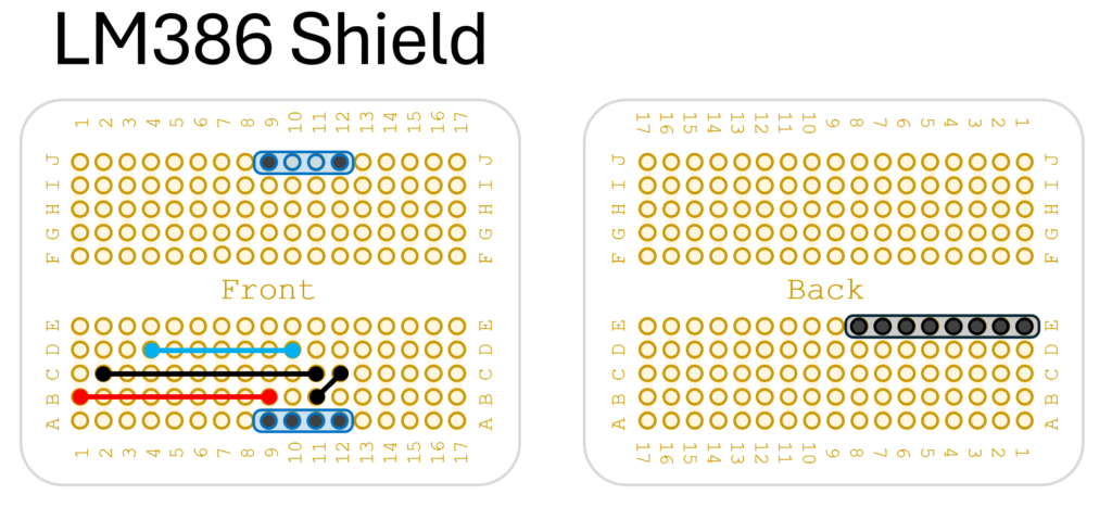
Shield Instructions
- Solder a 15mm blue wire from D4 to D10
- Solder a 22mm black wire from C2 to C11
- Solder a 4mm black wire from B11 to C12
- Solder a 20mm red wire from B1 to B9
- Solder a 4pin male header at A9, A10, A11, and A12. This is where the inverted female header of the LM386 will be mounted. Note the silkscreen on the module to make sure A9 is VCC, A10 is IN, and A11 and A12 are both GND.
- Solder a 4pin male header (with center pins removed) at J9 and J12 (this will just hold an empty female header shell to support the far end of the LM386
- Solder an 8pin male header on the Back side of the board from E1 to E8, with the long pins pointing down (this is where the LM386 Shield will mount to the Audio Shield).
The other problem you’ll find with the LM386, is that it simply may not amplify enough to use it outside without distorting the audio. If you think that will be an issue, try the next option instead…
TDA2050 Mono Audio Amplifier Module
Just looking at this module, you can see it’s built for more serious work. A massive heat sink, two giant capacitors, and an actual potentiometer for adjusting volume without a screwdriver. It’s a much simpler solution. A more expensive solution to be sure, but it generates between 5-120 Watts of output. And no need to muck about with the piggy-back module. Just set this alongside the Audio shield.
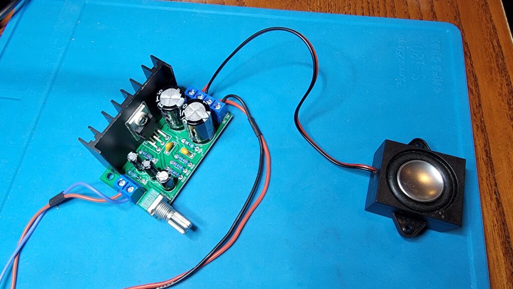
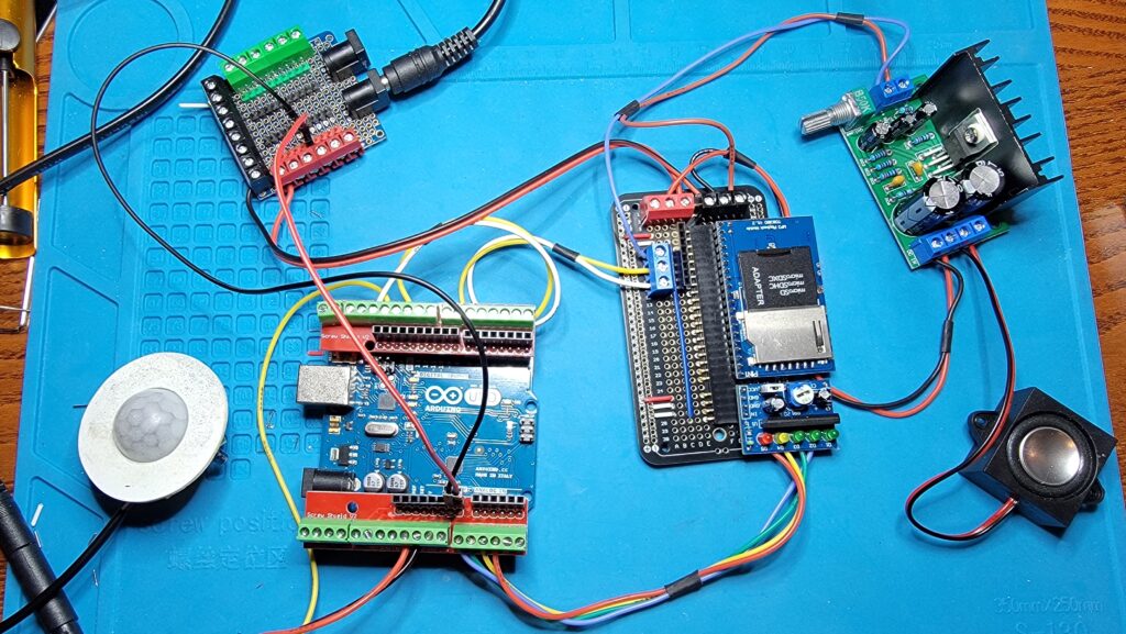
Audio Code
I started by adding the serMP3.h and serMP3.cpp files to my project. The Arduino code that proves it works is very simple:
#include <Arduino.h>
#include <serMP3.h>

const int TxPin = 10;
const int BusyPin = 13;

serMP3 MP3(TxPin, BusyPin);

void setup()
{
  // put your setup code here, to run once:
  Serial.begin( 9600 );
  Serial.println("Begin Run");

  MP3.begin(31);  // Turn up the TDB380 volume all the way
}

// I put 7 audio files on the SD card
int track = 1;
int numtracks = 8;

void loop()
{
  // put your main code here, to run repeatedly:
    Serial.print( "Play Track #" );
    Serial.println( track );

    MP3.play( track++ );    // Play the next track in the sequence
    if ( track > numtracks )
      track = 1;
    delay( 10000 );         // Wait 10 seconds
}
This code will sequentially loop through a number of tracks on the SD card. It isn’t checking to make sure the track has ended, it just fires off a new play command every 10 seconds.
The Jaw
For the next part to work, you need a servo motor that controls the jaw on a skeleton. I recommend looking at the Smart Head page to see how I put mine together. But, let’s assume you have that already. You have a servo motor, capable of operating in a range of values (usually traversing up to 180 degrees of motion by being assigned a value between 0 and 1023. Even if the servo can travel that distance, the jaw itself probably cannot. Therefore, you have to (usually through trial and error), identify the workable range of motion of the servo. Once you determine that Min and Max value, you can create code that will limit motion to within that range.
I2C Bus
Say for example you have a 3-axis skull you want to control. That’s 3 servos for nod, tilt and turn plus one more for the jaw. Then you have RGB led’s that use up three more channels. I’m not saying you can’t find 7 spare channels, but out of 13 digital pins on the uno, pins 0 and 1 are handling your serial debugging, pin 13 is your audio busy flag. pin 12 is reading your motion sensor. pin 10 is commanding your audio. That leaves 3,4,5,6,7,8,9,11 … that’s most of the remaining outputs. Yuck. So, what do we do instead? Allow me to introduce you to the glories of the I2C bus, and the PCA 9685, 16 Channel, 12Bit PWM Servo Motor Driver Board Controller.
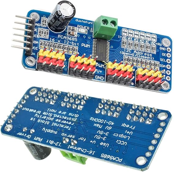
It’s an addressable module that can be programmed with its own clock speed, and by only using up two pins on the Arduino, you gain 16 additional PWM outputs. It’s logic runs on 3-5Vdc, which means you can drive it from the 3.3v output of the Arduino, while maintaining a completely separate power supply to drive the servo itself.
The I2C bus uses two channels, a clock (SLC) and a signal (SDA) to communicate between multiple masters and multiple slave devices. Each device on the bus gets its own address, and families of devices have similar address ranges. In the Arduino world, a variety of I/O expanders work with this protocol. The only downside is that the bus has a limited range before the signal degrades. Depending on shielding, the signal might make it 2 meters. There are repeaters and signal boosters available. At any rate, I decided to leverage the I2C bus for this project.